


Validating High-Speed Measurements: Clock and High-Frequency Signals
In high-speed hardware debugging, one of the first questions engineers need to answer is simple but critical:
Is the information we are measuring really correct?
The answer depends not only on the circuit under test, but also on the measurement method, the probe, and the instrument used to observe the signal.
This article presents two practical examples: first, the measurement of a clock signal, and then the measurement of a high-frequency differential signal. The objective is to show how the selected probe and measurement mode can affect the waveform, the measured amplitude, and the interpretation of the signal.
The measurements shown in the following sections were performed using a Siglent SDS1052DL+ oscilloscope for time-domain waveform observation and a GWINSTEK GSP-730 spectrum analyzer for frequency-domain analysis.
1. Clock signal path
Before comparing the measurement results, it is important to define the signal path used as a reference.
In this example, the signal under analysis is a high-speed differential clock signal. Although it can be observed from one line to ground, the relevant signal is the voltage difference between the positive and negative lines.
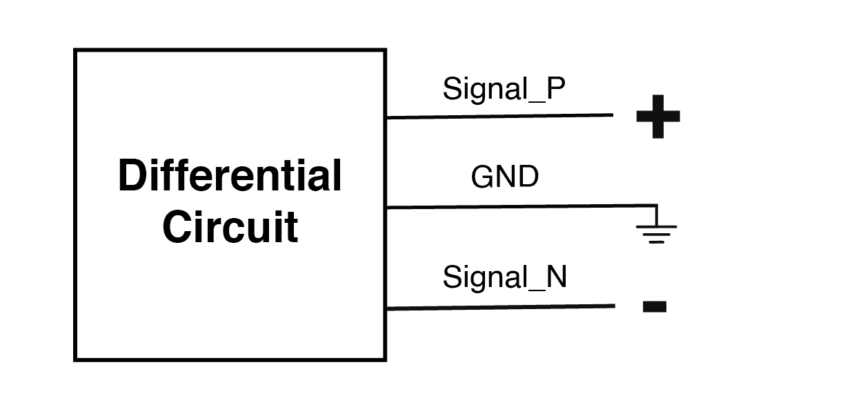
This signal path is used to compare how different probing methods affect the observed waveform and measured amplitude. In high-speed measurements, the result depends not only on the circuit, but also on the probe and the way the signal is connected to the instrument.
2. The problem: passive probe measurement
After identifying the signal path, the first measurement was performed using a conventional passive probe.
A passive probe is useful for many general-purpose measurements. However, when observing high-speed or differential signals, it may provide only a partial view of the signal. This is because a passive probe typically measures one point with respect to ground, while the real signal behavior may depend on the voltage difference between two signal lines.
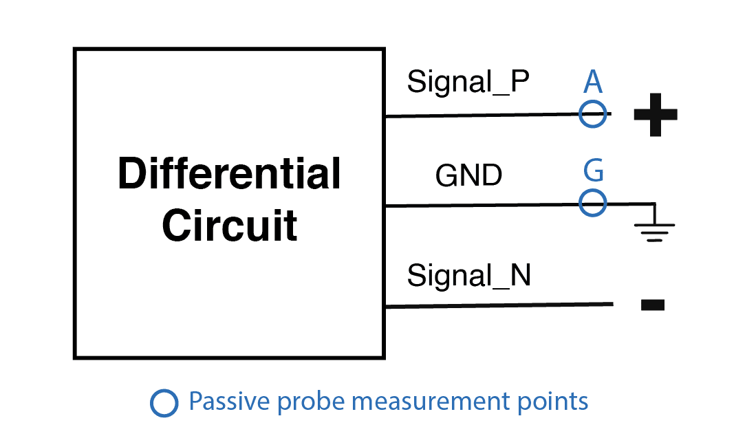
When the signal was observed with the passive probe, the waveform appeared more triangular and lower in amplitude. The measured amplitude was approximately 272 mVpp at 50 MHz.
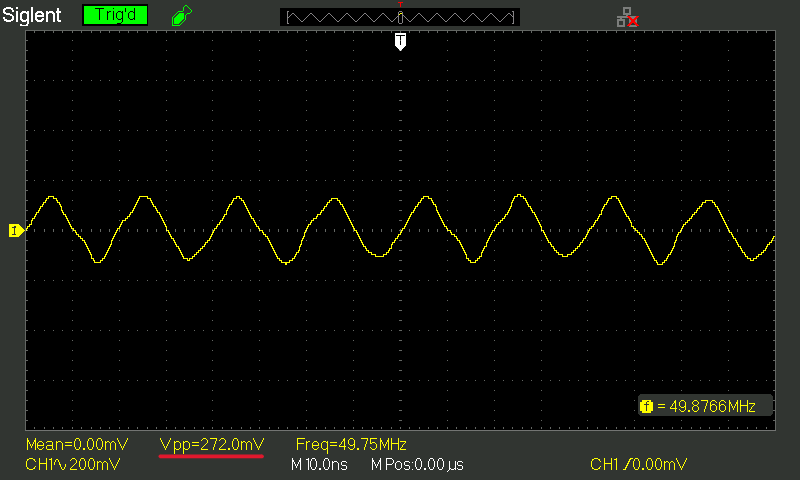
This result does not necessarily mean that the signal itself is incorrect. It shows that the measurement method can influence the waveform shape and the measured amplitude.
In high-speed signal measurements, a passive probe may affect the result due to:
| Passive probe effect | Possible consequence |
|---|---|
| Capacitive loading on the measured node | Signal deformation or amplitude reduction |
| Single-ended observation of a differential signal | Incomplete interpretation of the actual clock signal |
| Ground lead or ground reference | Noise, ringing, or measurement artifacts |
| Imbalance between differential lines | A waveform that may not fully represent the differential signal behavior |
3. Active differential probing
To compare the passive probe result with a differential measurement, the same signal path was measured using the CE-DP1000V1 Active Differential Probe.
Unlike a conventional passive probe, the active differential probe is designed to measure the voltage difference between two circuit nodes. In this case, the signal is measured between the positive and negative lines.
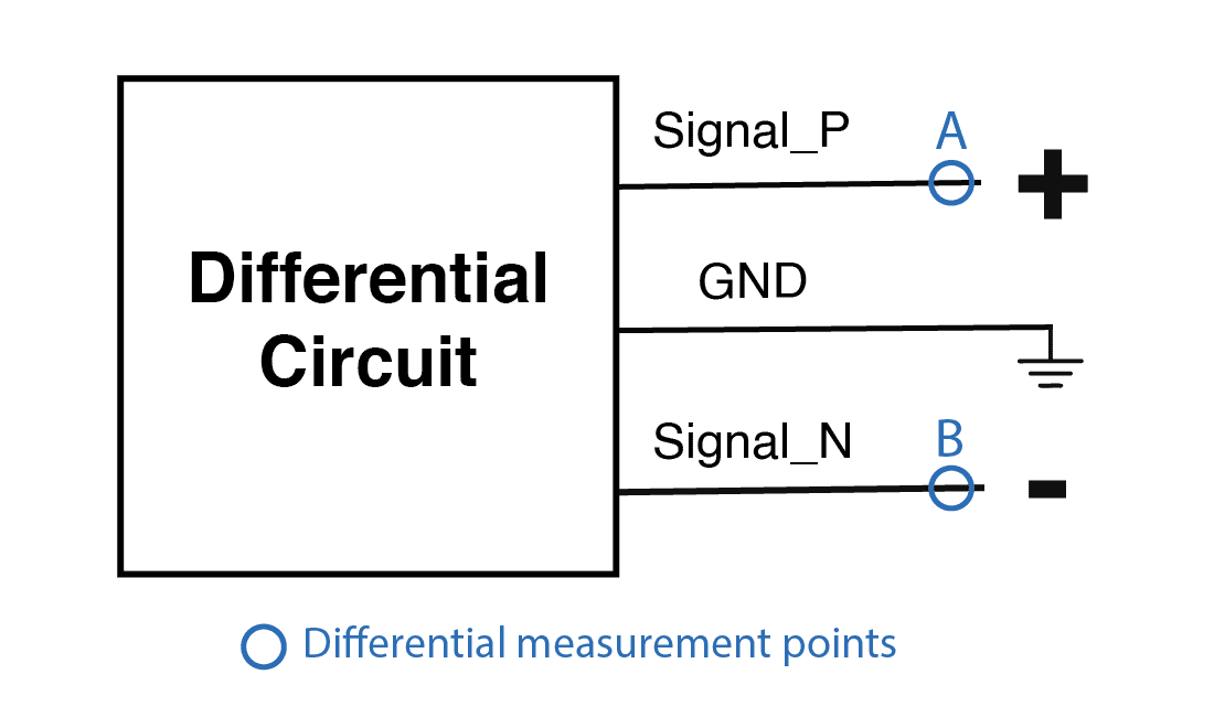
In differential mode, the probe measures the voltage between Tip A and Tip B, providing the difference between both voltages:
VDIFF = VA − VB
This allows the differential signal to be observed while reducing the influence of ground-reference effects and single-ended interpretation.
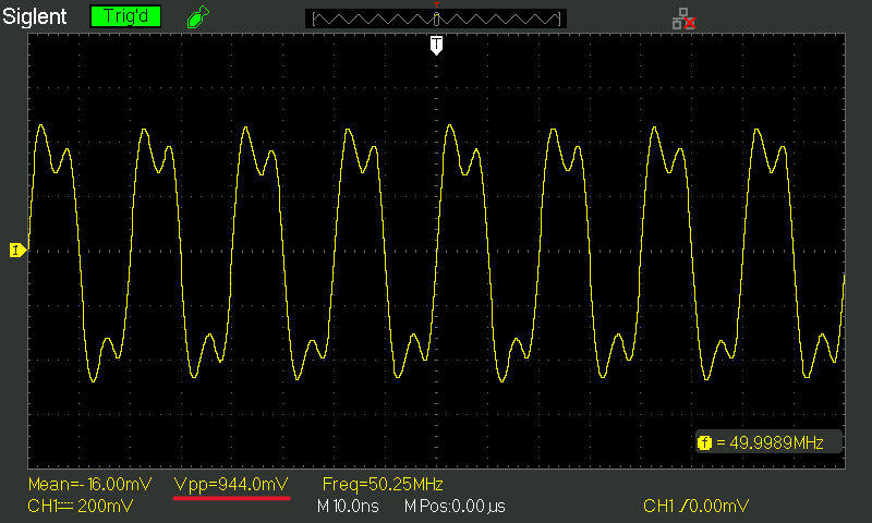
With this measurement approach, the signal is evaluated as a voltage difference between two nodes. Compared with the passive probe measurement, the active differential measurement shows a larger amplitude and a clearer waveform.
4. Direct comparison: passive probe vs active probe
The direct comparison between both measurements shows how probe selection can affect the observed waveform in high-speed debugging.
With the passive probe, the waveform appears smaller and more triangular, with an amplitude of approximately 272 mVpp. With the CE-DP1000V1 Active Differential Probe, the waveform appears larger, with an amplitude of approximately 944 mVpp, because the signal is measured differentially.
Figure 6. Clock signal comparison using a passive probe and the CE-DP1000V1 Active Differential Probe.
Single-ended vs differential clock measurement
A second comparison was made using the active probe itself: observing the same clock signal in single-ended mode and in differential mode.
This comparison is important because the measured amplitude can change depending on how the signal is observed. A single-ended measurement references one side of the signal to ground, while a differential measurement observes the voltage difference between the two signal lines.
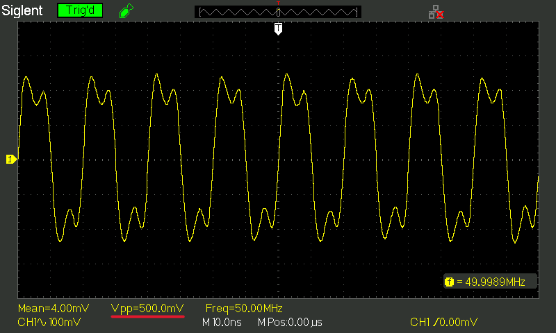
In the single-ended view, the measured amplitude is approximately 500 mVpp. In the differential view, the measured amplitude is approximately 944 mVpp.
This comparison shows that the waveform shape is not the only relevant parameter. The measured amplitude can also change significantly depending on the measurement mode.
For differential clock paths, comparing single-ended and differential measurements helps engineers better understand how the signal is being observed and avoid underestimating the signal level.
Spectrum analyzer comparison of the clock signal
The clock signal was also evaluated in the frequency domain using a spectrum analyzer. This helps verify not only whether the clock frequency is present, but also how the measured signal level changes depending on the probing method.
In this case, the clock signal was measured around 50 MHz using three approaches:
| Measurement method | Marker level at 50 MHz |
|---|---|
| Passive probe | -15.2 dBm |
| Active probe, single-ended mode | -2.2 dBm |
| Active probe, differential mode | -7.7 dBm |
Passive probe vs Active Differential Probe
The first comparison is between a conventional passive probe and the CE-DP1000V1 Active Differential Probe measuring the clock signal in differential mode.
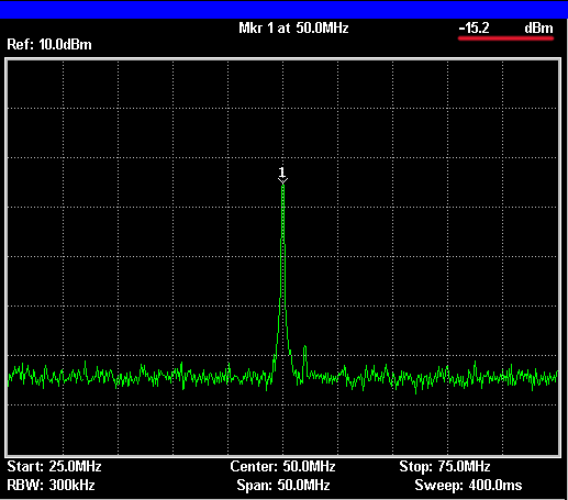
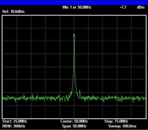
The difference between both measurements is significant. The passive probe shows approximately -15.2 dBm, while the active differential probe shows approximately -7.7 dBm at the same clock frequency.
The difference is calculated as:
-7.7 dBm − (-15.2 dBm) = 7.5 dB
This means that, in this measurement, the active differential probe reads about 7.5 dB higher than the passive probe.
This comparison shows that the measured level of the same clock signal can change significantly depending on the probing method. In this case, the active differential probe provides a higher measured level than the passive probe, which helps reduce the risk of underestimating the signal in the frequency domain.
The active differential probe is more suitable for this type of measurement because it observes the signal differentially and is designed for high-speed signal validation.
Single-ended vs differential measurement with the Active Probe
The second comparison uses the same active probe, but changes the measurement mode: single-ended versus differential.
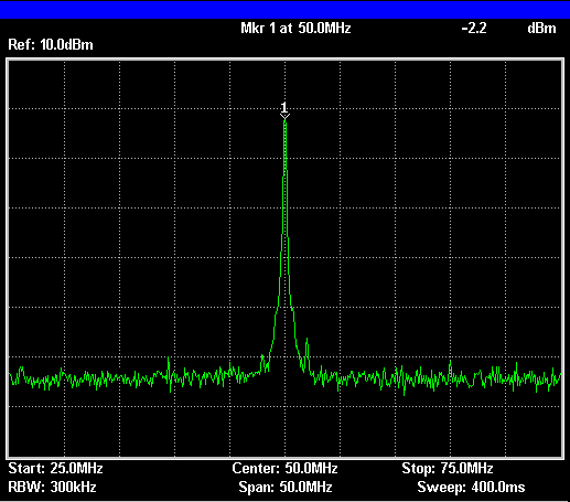
In single-ended mode, the measured clock level is approximately -2.2 dBm. In differential mode, the measured level is approximately -7.7 dBm. This represents a difference of about 5.5 dB between both measurement modes.
This comparison shows that the selected measurement mode can significantly affect the observed signal level in the spectrum analyzer. A single-ended measurement and a differential measurement may produce different amplitude readings, even when observing the same clock frequency.
For clock validation, this means that the engineer should not only check whether the 50 MHz component is present. The measurement mode also matters because it directly affects the observed signal level.
Key takeaway
The same clock signal can appear very different on a spectrum analyzer depending on the probe and measurement mode used.
| Comparison | Result |
|---|---|
| Passive probe vs active differential probe | Active differential measurement is about 7.5 dB higher |
| Active single-ended vs active differential | Differential measurement is about 5.5 dB lower |
Spectrum analyzer comparison of the high-frequency output signal
A second frequency-domain comparison was made at a different measurement point: the high-frequency output signal.
Unlike the previous case, this is no longer the input clock path. Here, the signal under test is the differential high-frequency output of the circuit, observed around 1 GHz using a spectrum analyzer.
This comparison is especially important because, at higher frequencies, the limitations of a conventional passive probe become more evident. Signal attenuation, loading effects, and reduced high-frequency fidelity can significantly affect the measured result.
Passive probe vs Active Differential Probe
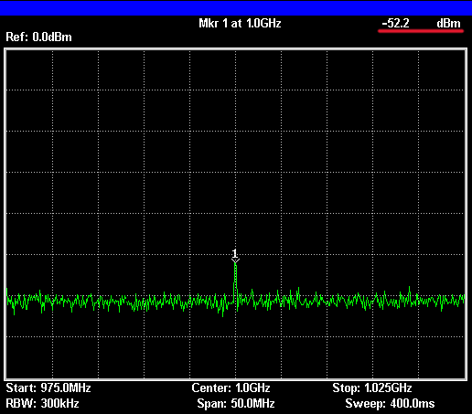
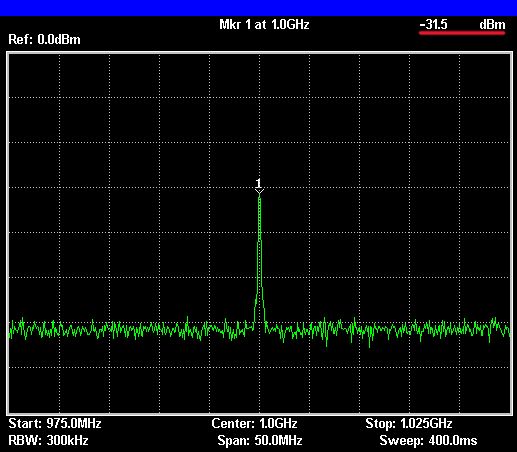
The difference between both measurements is clear. With the passive probe, the high-frequency signal appears at approximately -52.2 dBm, while the active differential probe shows approximately -31.5 dBm. This is a difference of about 20.7 dB.
| Measurement method | Marker level at ~1 GHz |
|---|---|
| Passive probe | -52.2 dBm |
| Active differential probe | –31.5 dBm |
This result highlights the benefit of using an active differential probe for high-frequency differential signals. At these frequencies, the passive probe introduces much higher apparent attenuation, making the signal look significantly weaker than it actually is.
By contrast, the CE-DP1000V1 Active Differential Probe is better suited for this type of measurement and shows a much stronger signal level, providing a more representative view of the actual clock signal path.
This comparison reinforces an important practical point:
At high frequencies, probe selection has a direct impact on the measured signal level.
A passive probe may still detect the signal, but it can substantially underestimate its amplitude. The active differential probe reduces this effect and is therefore more appropriate for validating high-frequency differential outputs such as clock signals.
5. Why the CE-DP1000V1 helps
The CE-DP1000V1 Active Differential Probe is designed for high-frequency and differential signal measurements. Its key characteristics help reduce circuit loading and provide a more faithful reading of the signal.
| Specification | CE-DP1000V1 |
|---|---|
| Bandwidth | 1.0 GHz |
| Input resistance | 2 MΩ |
| Input capacitance | < 1.2 pF |
| Input dynamic range | ±2 V |
| DC attenuation | 1:1 ±2% |
| Power | 5 V via USB |
| Output | SMA RF connector |
These specifications make the probe suitable for high-speed signal analysis, digital system validation, RF measurements, mixed-signal debugging, and low-disturbance differential measurements.
In this case, its main advantage is that it measures the voltage difference directly between the positive and negative inputs of the differential signal, instead of observing only one line against ground.
This helps answer the original question with greater confidence:
Is the clock signal being measured correctly?
6. Conclusion
In high-speed hardware debugging, the waveform displayed on the oscilloscope does not always faithfully represent the real signal in the circuit. This is especially true for differential clock paths and other sensitive high-frequency nodes.
In this case, the objective was to validate whether a high-speed clock signal was being measured correctly. The passive probe measurement showed a smaller, more triangular waveform that could suggest a signal integrity issue. However, the active differential measurement showed a larger, more square-like waveform, providing a more appropriate way to observe the signal.
This comparison highlights why probe selection is fundamental. A passive probe may introduce loading, ground-reference effects, or a misleading single-ended view. An active differential probe helps reduce these effects, allowing engineers to validate the signal with greater confidence.
The CE-DP1000V1 Active Differential Probe helps engineers reduce measurement-induced errors and make better decisions during high-speed debugging.
Measure the clock signal — not the probe effect.
Measure the Signal, Not the Probe Effect
The CE-DP1000V1 Active Differential Probe from Coffee Electronics is designed for low-disturbance measurement of high-speed differential signals. With 1 GHz bandwidth, high input impedance, and low input capacitance, it helps engineers validate clock signals, RF stages, and sensitive high-frequency nodes with greater confidence.
Measure the clock signal — not the probe effect.
Interested in improving your high-speed signal measurements?
Learn more or request a quote for the CE-DP1000V1 Active Differential Probe:
Discover more Coffee Electronics solutions. In addition to our Active Differential Probe, we are developing products such as eLABin1, an all-in-one electronic laboratory platform, and Coffee Sense, an IoT sensing system designed for real-time monitoring and embedded applications.